Introduction
Water transport in trees can be limited by cavitation. Cavitation is the breaking of the water column that follows atmospheric demand and transpiration increase and/or soil water content decrease, particularly in drought conditions. Cavitation initiates in the cells of the conductive xylem (tracheids in conifers) when the cell water copes with increasing tensions (Hacke and Sperry 2001) and turns from a liquid metastable state to a more stable gaseous state (Cruiziat et al. 2002, Tyree and Zimmerman 2002, Mayr et al. 2014). According to the air-seeding hypothesis, cavitation propagates from cell to cell as air is aspirated from a non-functional air-filled tracheid into a conductive one through the inter-tracheid pits (Delzon et al. 2010). Little information is available about where exactly cavitation springs up in a tree-ring and how it propagates inside it. Domec and Gartner (2002) have studied vulnerability to cavitation of earlywood and latewood in Douglas-fir (Pseudotsuga menziesii (Mirb) Franco) finding that latewood was more vulnerable to cavitation at high trunk water potentials than earlywood. This suggests that cavitation could start in latewood, and then spreads to earlywood. The dynamics of cavitation initiation and propagation within the growth ring may have important functional implications since if water is released from cavitated latewood this could decrease earlywood tension (capacitance function, Meinzer et al. 2009) leading to ks maintenance during drought. However, if cavitation initiates on the largest tracheids of earlywood, this may result in a strong and early decrease in ks.
Earlywood is produced in temperate climate during the first part of the growing season. In conifers, earlywood is formed of large-lumen, narrow-wall low-density tracheids. Latewood is produced later during the growing season, generally when atmospheric demand increases, soil water content depletes and photoperiod decreases. Latewood is formed of narrower-lumen, thicker-wall denser tracheids. The transition from earlywood to latewood is more or less gradual according to the species (Ivkovich and Rozenberg 2004) and the cambial age (Zobel and Sprague 1998). Conventionally, tree-rings are cut into earlywood and latewood. This action arbitrarily splits the transition zone and mixes it with earlywood and latewood. Some authors have suggested that it may be useful to separate the transition zone from earlywood and latewood, cutting the ring into three parts (Rozenberg et al. 2004, Franceschini et al. 2013), thus defining more homogeneous earlywood and latewood. As a matter of fact, Dalla-Salda et al. (2011) found a stronger relationship between wood density and resistance to cavitation when they used the homogeneous first part of the earlywood rather than the conventionally-defined heterogeneous earlywood.
Changes in ring structure may result in changes in the hydraulic architecture of plants with direct consequences on water supply to the leaves and tree growth and/or survival (Froux et al. 2002, De Micco et al. 2008, Martinez-Meier et al. 2008, Hoffmann et al. 2011). Tree-ring structure can be thoroughly described using X-ray microdensity profiles (Polge 1966). Wood microdensity is determined by cell dimension: it describes the proportion of cell wall in a given woody tissue. This proportion reflects wood mechanical and functional properties (Zobel and van Buijtenen 1989, Hacke and Sperry 2001, Hacke et al. 2001) that are related with the three wood functions: the mechanical support of the body of the plant (Zobel and Sprague 1998), the storage of water and biological chemicals (Stratton et al. 2000) and the safe and efficient transport of water from the roots to the leaves (Maherali et al. 2004, Pitterman et al. 2006,). Determinist relationship between wood density and vulnerability to cavitation is unclear. Several studies found positive correlations (Hacke and Sperry 2001, Rosner et al. 2007, Dalla-Salda et al. 2009, 2011), while others reported a lack of relationship (Lamy et al. 2012).
The present study had three objectives: 1) to investigate the dynamics of embolism formation within the tree-ring of Douglas-Fir; 2) to compare the dynamics of tracheids embolism within the tree-ring between resistant and vulnerable trees; and 3) to determine whether the variation found between resistant and vulnerable trees (if any) in terms of dynamic of embolism formation could be related with the microdensity structure of the ring. Initiation and propagation of embolism in the ring were studied for homogeneously-defined earlywood, latewood and a separate transitional zone by means of analyses of images of stained wood surface and X-ray microtomography of wood samples taken at variable embolism levels from exposure to different pressure intensities. X-ray microtomography appears now as a reference technique for embolism visualization in xylem (Cochard et al. 2014), but as it’s, a time-consuming method, only one resistant to cavitation tree was analyzed. We applied the staining method analysis to eight Douglas-fir trees selected for their differential resistance to cavitation: the four more resistant and the four more vulnerable among a set of fifty trees. Microdensity profiles of wood samples of the same 8 trees were studied with x-ray methodology (Polge 1966). To our knowledge, there is no study documenting the intra-ring dynamic of embolism formation in relation with microdensity.
Materials and methods
Plant Material
The studied plants were 11 years old Douglas-firs from a genetic trial belonging to INTA (Instituto Nacional de Tecnología Agropecuaria, Argentina) near Trevelin, Patagonia - Argentina (43° 06' S - 71° 32' W).
Firstly, stem vulnerability to cavitation (VC) curves were obtained with the air injection method (Cochard et al. 1992) on 50 trees from 10 different genetic entities. In order to characterize the trees for their resistance to cavitation, the wood samples were taken from the stem portion corresponding to the last ring (year 2011), following the methodology described in Dalla-Salda et al. (2009, 2011).
Based on the P50 (50% percent of conductivity loss) calculated on their VC curves (see Table 1 in Results section), eight trees were selected for a detailed study of embolism propagation within the growth-ring: the four most resistant and the four most vulnerable to cavitation.
Dynamics of embolism propagation studied through staining method:
From the eight selected trees, 30 cm long longitudinal samples from the 2011 ring were taken, next to the samples used to obtain the vulnerability curves. Each of these longitudinal samples was cut under water into six 5-cm-long segments. Each portion was subsequently subjected to a different pressure level (0, 1, 2, 2.5, 3 and 3.5 MPa) by means of a pressure chamber (Model 1000 Pressure Chamber Instrument, pms instruments, Co. USA) with its distal end protruding from the chamber. After being submitted to a given pressure level the sample was connected to a water column with deionized and distilled water colored with Phloxine 1% in order to stain the conductive area. The samples were then oven dried and cut in half. One of the middle surfaces was polished and digitalized. The obtained images were divided in earlywood (EW), transition-wood (TW) and latewood (LW) zones as described in the next section, and then the percentage of the stained (i.e. conductive) area was measured in each type of wood with ImageJ image analysis software (Rasband 2009), Fig. 1 Subtracting this area to the total conductive area, the variable named “% of non-conductive area” was estimated assuming that it represents a measure of the proportion of cavitated (embolized) cells in the sample.
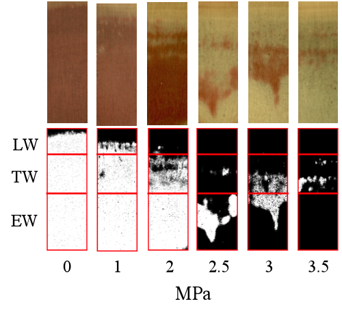
Figure 1: Examples of wood samples (photographs taken in a binocular loupe and corresponding scanned images) subjected previously to different pressure levels (MPa) showing conductive (red-stained) and non-conductive areas.
Wood microdensity:
Microdensity profiles were obtained from wood samples of the 8 selected trees using indirect x-ray microdensitometry (Polge 1966). The resulting films were scanned and processed with WinDENDRO software (Guay et al. 1992). A function written in R-language (R Core Team 2014) allowed dividing each 2011 ring into three parts: earlywood, transition-wood and latewood (hereafter EW, TW and LW, respectively). The function firstly identifies the minimum (MID) and maximum ring density (MAD), calculates the average density of these two extreme values and locates it along the x axis (Mdp: red vertical line in Fig. 2) as in Mothe et al. (1998). At this point the ring is divided in two parts, corresponding to the conventional EW and LW portions. Subsequently the R function repeats the extreme average procedure described above in each part of the ring, defining Mdp1 (Mdp1: blue vertical line in Fig. 2) and Mdp2 (Mdp2: green vertical line in Fig. 2). The TW is finally defined as the portion of the ring located between Mdp1 and Mdp2. For each ring the following microdensity variables were calculated: ring width, ring density, EW width, EW density, TW width, TW density, the slope describing the increment of wood density within the transition-wood portion (slope), LW width and LW density.
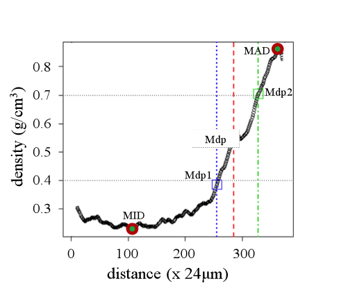
Figure 2: Ring microdensity vs. radial distance in the stem (one ring was analyzed). The following variables are shown on the graph: the minimum and maximum wood density (MID and MAD, respectively), the mean density point of the ring (Mdp), the mean density point for the intial and final part of the ring (Mdp1 and Mdp 2, respectively).
We obtained the length of each portion by multiplying the number of density points in each part of the ring per 24 µm (distance between each point of microdensity measurement). These measures were plotted on the stained wood surface images and were used to divide them into three parts matching the EW-TW-LW division in the corresponding ring microdensity profile (Fig. 1).
A t-test (p<0.05) was assessed to compare percentage of non-conductive area at the different pressures between the parts of the ring and between the resistant and vulnerable trees. The same procedure was used to compare the differences between the resistant and vulnerable trees for the microdensity variables.
A standardized tree-ring microdensity profile was computed to describe the intra-annual density variation along a common scale for both groups of trees. Each of the 2011 tree-rings was described by 33 density points by gathering and averaging microdensity values. For this purpose, significant difference between resistant and vulnerable trees was assessed by a t-test at the level of each density point (p< 0.05).
Embolism visualization by microtomography:
Xylem embolism was visualized by using x-ray microtomographic scans recorded in the PIAF laboratory (INRA, Clermont-Ferrand, France), under the same conditions as in Cochard et al. (2014). Brodersen (2013) and Torres-Ruiz et al. (2014) were the first to show xylem vulnerability to embolism using x-ray microtomographic scans. The great advantage of x-ray microtomography is the three-dimensional observation of internal structure of samples without cutting and surface preparation. One longitudinal sample was taken as described above from a single tree selected in a resistant to cavitation family of a Douglas-fir progeny trial located at Ecouves, Normandy, France (unpublished data). The sample was cut under water in three portions, 5 ×5 mm in the transversal section and about 20 mm in the longitudinal direction. Two of them were submitted to hydraulic tensions by centrifugation in the Cavitron device (Cochard et al. 2005). The two centrifugation speeds were chosen in order to generate respectively -2.5 and -4 MPa that caused respectively 50 and 88 % loss of conductivity.. After centrifugation, the samples were immediately dropped in liquid paraffin wax and cooled in order to prevent their drying during the x-ray scan. The samples were then placed in the X-ray microtomograph (Nanotom 180 XS, GE, Wunstorf, Germany). X-ray source settings were 50 kV and 275 μA. After 3D reconstruction, the field of view was a 6.2 × 6.2 × 6.2 mm3 with a spatial resolution of 2.8 × 2.8 × 2.8 μm per voxel. One radial-tangential 2D cross section was virtually extracted from the middle of the volume in order to visualize the part of the ring located in the middle of the sample, using VGStudioMax software (Volume Graphics, Heidelberg, Germany). Then, images were analyzed using the ImageJ software in order to compute the percentage of cross section area that was embolized.
Results
Vulnerability to cavitation:
Mean and standard deviation of P12, P50, P88 and slope of the 50 trees for which the vulnerability to cavitation curves were obtained are shown in table 1. The resistant and vulnerable trees (n=4) were selected by their contrasting P50 values. Mean ± standard deviation of P50 of resistant and vulnerable trees were -3.32 ± 0.18 and -2.44 ± 0.18 MPa, respectively (see Fig. 3).
|
|
Descriptive statistic |
|
|
Variable |
Mean |
Standard deviation |
|
P12 |
-0.97 |
0.55 |
|
P50 |
-2.99 |
0.34 |
|
P88 |
-4.04 |
0.32 |
|
slope |
36.03 |
11.31 |
Table 1: Mean and standard deviation of the variables describing the VC of the fifty evaluated trees.
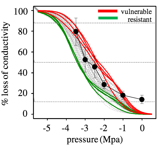
Figure 3: Vulnerability to cavitation curves of 50 Douglas-fir trees (grey lines), from which the four most vulnerable (red lines) and the four most resistant to cavitation (green lines) were selected for the present study. Black line with black full circles shows the % of non conductive area for the whole ring constructed by the staining method.
Propagation of embolism within the growth ring:
Considering all analyzed trees, in the EW the % of non conductive area is very close to 0% at atmospheric pressure and at -1 MPa. It increases slowly to around 10% at -2 MPa, and then rapidly rises to more than 80% between -2 and -3.5 MPa (see Fig. 6 in next section, which shows the common general pattern of vulnerable and resistant trees). At all pressure levels the % of non conductive area is significantly lower in the EW than in the LW, except at -3.5 MPa where there is no significant difference between both parts of the ring (Table 2).
In the TW the % of non conductive area is significantly different from the one in the EW at -2 MPa, where it is significantly higher, and at -3.5 MPa, where it is significantly lower (Table 2).
|
|
Pressures (MPa) |
|||||
|
Tested ring parts |
0 |
1 |
2 |
2.5 |
3 |
3.5 |
|
EW - TW |
ns |
ns |
0.0045 |
ns |
ns |
0.0461 |
|
EW - LW |
0.0003 |
2.77e-07 |
2.94e-12 |
0.0005 |
0.0047 |
Ns |
|
TW – LW |
0.0005 |
4.81e-08 |
1.61e-06 |
0.0011 |
0.0009 |
0.0317 |
Table 2: Probabilities associated to Student t-test for the comparison of the percentage of mean non-conductive area between the different parts of the ring (EW= earlywood; TW= transition-wood; LW=latewood)
Partly in agreement with the observations made from staining wood samples subjected to different pressure levels, the microtomography image of a sample at atmospheric pressure shows that all tracheids were water filled (are conductive) in the three parts of the ring (Fig. 4A). The same conclusion was obtained for EW and TW from the staining method, but a high proportion of non-conductive area was observed in LW even at atmospheric pressure, which could be interpreted as embolized tracheids if microtomography images were not available. This novel method indicates that LW tracheids had water in their lumens at atmospheric pressure. Therefore, they were not stained at the very low pressures of ks determination due to their high resistance to water flow and not because they were cavitated.
The figure 4B shows the microtomography image of a sample that experienced a -2.5 MPa pressure that should accomplish for around 50% of conductivity loss (Fig 1 and Table 1). At this pressure, the x-ray observation enlightens that the LW region was greatly embolized. The EW portion showed low embolism and the TW was still fully water saturated.
Finally, the figure 4C shows a sample submitted to a -4 MPa pressure that should accomplish for 88% of conductivity loss (Fig.1, Table 1). The x-ray observation indicated clearly the EW and LW regions were largely embolized and only the TW region showed water in the lumens of the tracheids. Similarly, observation of the radial-longitudinal cross section of the sample submitted to -4 MPa allows to appreciate the dark grey strips corresponding to the empty lumens of the embolized tracheids both in the EW and in the LW parts of the ring (Fig. 5). Bright voxels (light grey strips) correspond to free water in the lumens, which are only located in the TW part of the ring (Fig. 5).
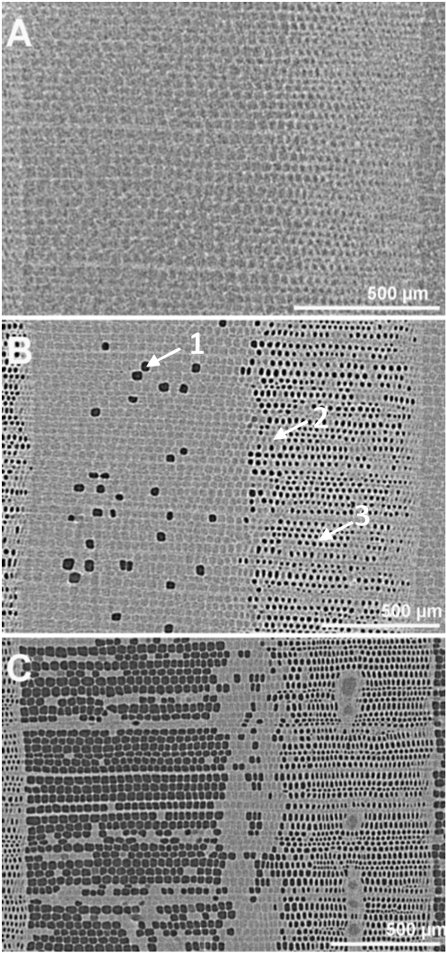
Figure 4: X-ray microtomographic images of a cross section of Douglas-fir. A: image of the control sample submitted to atmospheric pressure. B: sample submitted to a pressure of -2.5 MPa. C: sample submitted to a pressure of -4 MPa. The grey levels refer to the local x-ray absorption property. The black spots (1) correspond to the empty lumens of the embolized tracheids; the grey spots correspond to the water filled lumens (2) and the brighter clear segments correspond to the water saturated cell walls (3). The spatial resolution is 2.8 µm and the scale bar represents 500 µm.
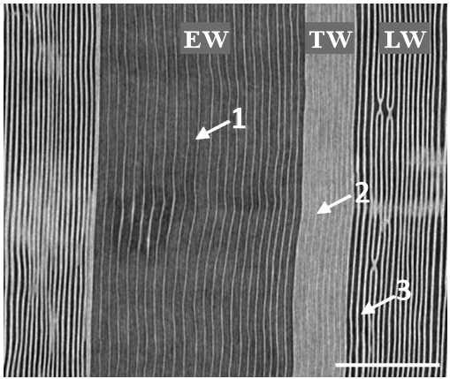
Figure 5: x-ray microtomographic radial-longitudinal cross section of Douglas-fir. The sample was submitted to a pressure of -4MPa. Dark grey strips (1) correspond to the empty lumens of the embolized tracheids. The bright strips (light grey) correspond to free water columns in the tracheids (2). Bright vertical lines correspond to water saturated cell walls (3). Spatial resolution is 2.8 µm. Scale bar is 500 µm.
Resistant vs vulnerable trees:
Figure 6 shows the variation of the % area of non conductive tracheids as a function of the applied pressure in the EW, TW and LW for the resistant and vulnerable trees.
In the LW, the % area of non conductive tracheids is nearly 80% at atmospheric pressure and increases to almost 100% at -3 and -3.5 MPa. As stated before from microtomography images, the high % of non conductive area at low pressures was not actually reflecting embolism, but only the high resistance to water flow in this portion of the growth ring. There was no significant difference between the resistant and the vulnerable trees in the proportion of non conductive area in the LW portion of the ring. In addition, there were also no significant differences in EW patterns of non conductive area between the resistant and vulnerable trees (Fig. 6).
In contrast, at -2 MPa there was a significant difference between the resistant and the vulnerable trees in the TW: the resistant trees showed a significantly lower % of non conductive area (Fig. 6).
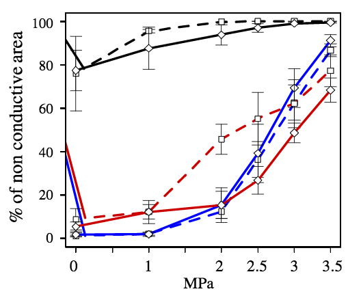
Figure 6: Percentage of non-conductive area in each type of wood (black, red and blue lines for the LW, TW and EW, respectively) in the resistant (diamonds with continuous lines) and vulnerable (squares with dotted lines) trees after being submitted to different pressure levels.
Regarding microdensity parameters, significant differences were found between the resistant and the vulnerable trees for ring width, EW width, TW width, and the slope and mean density of the TW (Fig. 7, only the variables with significant differences between the resistant and the vulnerable trees are shown). No significant difference was found for EW density nor for LW density. The resistant trees showed a significantly less dense TW with a less steep slope. The resistant trees showed also a wider 2011 ring with significantly wider TW and EW (Fig. 7).
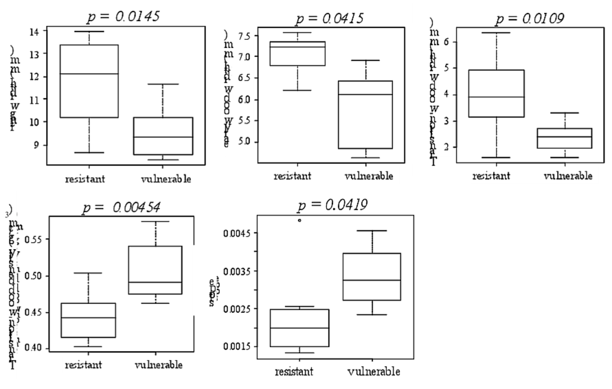
Figure 7 The microdensity variables for which significant differences were found between the vulnerable and the resistant to cavitation trees.
The significant differences between the resistant and the vulnerable trees are also viewed observing the standardized ring microdensity profiles (Fig. 8). The vulnerable trees have significantly higher microdensity values from the points 23 to 30 that effectively correspond to the TW part of the ring (Fig. 8).
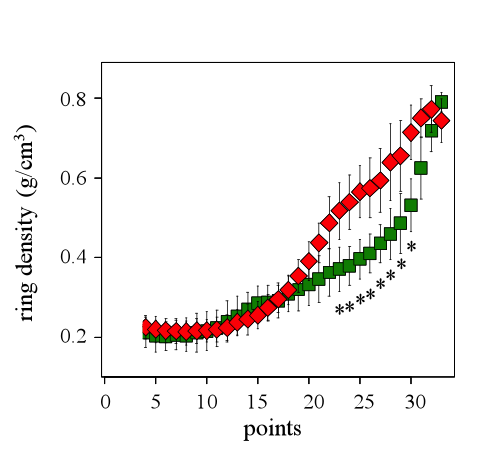
Figure 8: Standardized ring profile for the vulnerable (red diamonds) and the resistant (green squares) trees for the 2011 ring. Asterisks show significant differences (p<0.05) between of the resistant and the vulnerable trees for the microdensity values.
Discussion
Up to now, most VC curves published for woody plants were performed on branches, seedlings and roots (Cochard, 1992; Sperry and Ikeda, 1997; Kavanagh et al., 1999). As far as we know, little information is available from direct measures obtained on stem xylem of trees (Domec and Gartner, 2003). Our measurements of P50, achieved on trunk wood samples are consistent with those by other authors (Domec and Gartner, 2002) for the same species and are consistent with those of our previous studies (Dalla- Salda et al. 2009, Dalla- Salda et al. 2011). The VC curves of 50 Douglas-fir trees in this study were performed by the use of the air injection method. With 8 trees (the 4 most vulnerable and the 4 more resistant to cavitation) we computed the % of non conductive area for the 2011 whole ring by the staining method. Both methods seem to show the same types of curves and the % of non conductive area seem to be well represented by the % loss of conductivity (Fig. 3).
The dynamics of cavitation in the 2011 ring can be -in part- deduced from the plot in figure 6, which presents the curves describing the variation of the % of non conductive area with pressure. If we assume that the pressure increase along the x-axis of the plot simulates the condition of the start and development of a water deficit event, then these curves are likely to characterize the initiation and the propagation of cavitation in natural conditions. The observations of the stained samples images and of the microtomography images are generally consistent: the stained portions of the sample surface correspond to water filled lumen in the microtomography images, and the non-stained portions correspond mostly to embolized cells, with the exception of LW at atmospheric pressure. The results based on the stained samples images show that the LW is already mostly non-conductive at atmospheric pressure, while in the same conditions the EW and TW are either completely or nearly completely conductive. Although, the microtomography image (Fig. 4 A) shows that at atmospheric pressure the three parts of
the ring are full of water. This may be due to the fact that the microtomography is an image of the inside of a sealed sample, while the image of the stained surface is that of an open sample which has been handled and more exposed to air. Other hypothesis is that the difference found in the LW portion between the two methods is due to LW great resistance to water flux preventing stained water from arriving to that middle part of the sample were the images were done.
Both methods show the same trend in the initiation and propagation of the cavitation in the ring: the cavitation starts very early into the LW reaching more than 80% of non conductive area at -1 MPa and 100% between -2.5 and -3.5 MPa. This result confirms the findings by Domec and Gartner (2002) who state that the LW is more vulnerable to cavitation than the EW at high water potential.
The trend is completely different in the EW and TW, where the cavitation appears later, then propagates slowly between atmospheric pressure and -2 MPa, except in the TW of the vulnerable trees, where it spreads significantly faster than in the EW between -1 and -2 MPa. The % of non conductive area eventually reaches a high level in the EW (over 80%), similar (not significantly different) to that reached in the LW, while the TW remains with a significantly lower % of non conductive area (between 60 and 70%). This trend is similar in the microtomography images, except that the cavitation seems to start and propagate in the EW before propagating to the transition zone located between the EW and the LW, which remains mostly conductive at -4 MPa.
Hence it seems that cavitation occurs first in the LW, then “jumps” to the EW and TW (according to the stained samples images) or to the EW only (according to the microtomography images) and eventually to the TW. Thus, there are at least two successive events of cavitation initiation, the first one in the LW, then the second one in the EW. Whether there is a third initiation event in the TW or whether cavitation propagates from the EW to the contiguous TW cannot be inferred from our results. Assuming that the increase of the % of no conductive area corresponds to the propagation of the xylem cavitation, these results suggest that, in Douglas-fir, cavitation dynamic does not follow a trend linearly related to tracheid dimensions. According to Domec et al. (2006), pit number and dimension rapidly decrease from the EW to the LW. To our knowledge, no information has been published about the characteristics of the Douglas-fir TW pits. If we assume that the pits characteristics continuously vary from the EW to the LW, then cavitation propagation does not follow a trend linearly related to pits number and dimensions.
Published studies about the distribution of the pits and of their characteristics in radial-longitudinal (RL) and tangential-longitudinal (TL) cell-walls, show that in conifer species bordered pits are mostly located in the RL walls (Leitch and Savidge 1995, Domec et al. 2006, Kitin et al. 2009) rather than in the TL wall. In spite of we cannot extrapolate this pattern to all conifers, at least in Cryptomeria japonica, a temperate conifer, most of the EW tracheids lack of bordered pits in the TL walls, with the exception of the EW tracheids positioned next to growth-ring boundaries, whose tangential pits are connected with the previous ring’s LW tracheids (Kitin et al. 2009). In contrast to the EW, the LW tracheids commonly have bordered pits in the TL walls not only at the growth-ring boundary but also in the tracheid layers apart from it (Kitin et al. 2009). The TW tracheids also show bordered pits in the TL walls. The pit membranes in the RL walls have torus and margo with loosely arranged fibrils, with spaces (‘pores’) in between the fibrils. In contrast, no torus-margo structure and no pores are visible in the pit membranes of the TL walls of either the EW or LW tracheids. The bordered pits in the RL walls of the EW tracheids are much larger than those in the TL walls of the boundary EW tracheids. In the LW and TW, however, pits in the RL and TL walls are similar in size. In another study, Utsumi et al. (2003) found in three other conifers, that most of the bordered pits of tracheids are located in the RL wall; large-scale cavitation would be facilitated in the tangential direction when such tracheids are exposed to water stress. Moreover, these cells were formed at the same time and experienced the same growing conditions, thus we suggest that they developed the same sensitivity to cavitation. These results support our hypothesis of, at least two independent cavitation initiation events in the LW and the EW, followed by within EW and LW tangential spreading of cavitation that could be promoted by the characteristics of the pits in the TL tracheids walls.
The difference between the stained samples data and the observations on the microtomography images for the cavitation propagation trend could be related to the fact that in the stained samples images, the definition of the TW is based on the ring microdensity profile. Figure 1 shows that this so-called TW partly overlaps the stained portion of the ring and the non-conductive portion located on the LW side of the ring. In the tomography images, the zone located between the EW and the LW (Fig. 4C) seems on average much more conductive than the TW delineated on figure 1. This explains why on the figure 1 the % of non conductive area of the microdensity-defined TW is around 70% at -3.5 MPa while on the figure 4C the major part of the area of the zone located between the EW and the LW is formed of cells with water-filled lumens at 4 MPa.
There is no significant difference between the resistant and the vulnerable trees for the % of non conductive area in the EW and in the LW, whatever the pressure value. According to the tomography image, which was taken in a resistant tree, the TW remains the last conductive part during the progression of the cavitation in the ring. Both stained samples and microtomography results suggest that the TW would play a major role in the cavitation resistance..
Dalla-Salda et al. (2011) found that more resistant to cavitation trees had a higher mean density of an alternative EW density variable. In this study we also found significant differences between the resistant and the vulnerable trees for some alternative microdensity variables, but, these differences were found only for the TW portion: width, density and slope. Furthermore we found that the TW of the vulnerable trees is significantly denser than that of the resistant trees. The comparison of the average standardized rings of the resistant and vulnerable trees show the same trend (Fig. 8). At the level of the 50 trees among which were selected the four resistant and the four vulnerable trees of this study, there is no relationship between P50 and TW density (data not shown). Hence the significant difference observed in this study between the resistant and the vulnerable trees for TW density could be probably a selection artifact. Conversely, there is a significant negative relationship between P50 and TW width (r=-0.48 and p-value = 0.0008, data not shown) and there is a significant positive relationship between P50 and TW slope (r=0.50 and p-value = 0.0005, data not shown). These results are consistent with the significant difference found in this study between the resistant and the vulnerable trees for TW width and TW slope.
It is well-known that not only lumen dimension, but also pit number, dimension and characteristics play a major role in resistance to cavitation (Pittermann et al. 2010, Delzon et al. 2010, Bouche et al. 2014, Tixier et al. 2014). The air-seeding hypothesis predicts that xylem embolism resistance is linked directly to bordered pit functioning (Choat et al. 2008, Lens et al. 2013, Jansen et al. 2012). In any case, cavitation dynamics is still a controversial issue and not fully elucidated (Rockwell et al. 2014). According to Domec et al. (2006), the cell-walls of the Douglas-fir LW are punctured by a low number of small size bordered pits, while the EW cell-walls are punctured by a large number of big pits. The higher rigidity of the LW pits membrane would explain the LW low resistance to cavitation. Conversely, despite its high lumen-diameter and large number of big pits, the higher flexibility of the EW pits membranes would explain the EW higher resistance to cavitation. But what could explain the even higher resistance to cavitation of the TW? The TW is by definition a transition zone between the EW and the LW. Hence cell and pits characteristics could be intermediate between those of the EW and the LW: by its own nature, the TW cell-lumen diameter is intermediate between that of the EW and the LW. If we hypothesize that the TW pit dimension and pit number are also smaller than in the EW, but that the TW pit membrane is as flexible or nearly as flexible as that of the EW pits, then these variables would tend to confer to the TW a resistance to cavitation that would be higher than in the EW.
In addition we found that the resistant trees have a significantly wider 2011 ring, with significantly wider EW and TW and no change in the LW width: hence the increased resistance to cavitation of the resistant trees could be explained by this larger amount of more resistant to cavitation EW and especially TW. They also have a less steep microdensity slope, i.e. a more gradual lumen diameter decrease, which could also tend to increase the TW resistance to cavitation.
Conclusion
According to our results, the initiation and the propagation of the cavitation in a Douglas-fir tree-ring seems to follow a discrete trend, with at least two successive initiation events: at the very start of a water deficit episode, cavitation appears to initiate and propagate rapidly in the LW. Later, when the water deficit persists and increases, a second cavitation event begin and spread in the EW and eventually propagate to the TW, which remains the last conductive part in the ring before full cavitation. Whether cavitation actually propagates from the EW to the TW or whether it initiates for the third time in the TW is not known. Our results suggest that the TW may play a leading role in the between-tree variation of cavitation resistance and thus should be carefully considered when studying adaptation to drought.
The sampling procedure carried out in this research benefited from a “smart sampling” approach (Rosner et al. 2014): the samples used for measuring vulnerability to cavitation, conductivity and microdensity came all from the same annual ring (here the 2011 ring), increasing the probability to highlight significant relationships and differences. We used an original method to study the within-ring microdensity variation, defining a transition zone between the EW and LW, increasing the precision of the study and highlighting the major role of this intermediate part of the ring. Improving the definition method of the TW or dividing the ring into more than three parts will likely contribute to better explain the initiation and the propagation of the cavitation in the ring, as well as better explain other functional processes occurring in the ring.
While little data is available, within-ring variation of pits characteristics seem to have a high explanatory potential for propagation of cavitation in the ring. The ratio between the pit aperture and the torus diameters is an important correlate with cavitation resistance in conifers and could perhaps help elucidating differences in the resistance of EW and TW tracheids. In the near future, studies of resistance to drought should concentrate efforts on large scale investigation of within-ring variation of pits characteristics and of the relationships between such pits characteristics and cavitation.